Most Specified
// 01
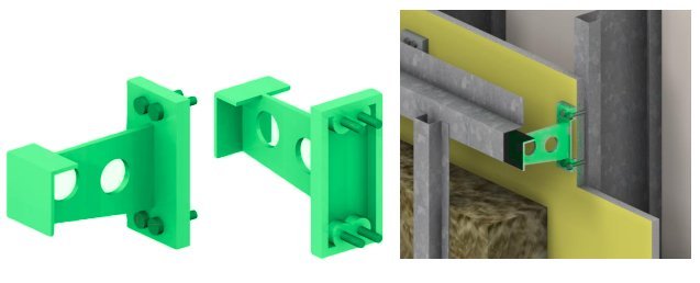
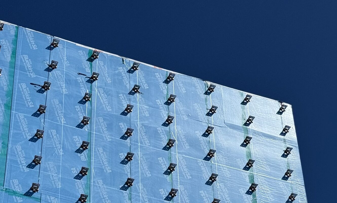
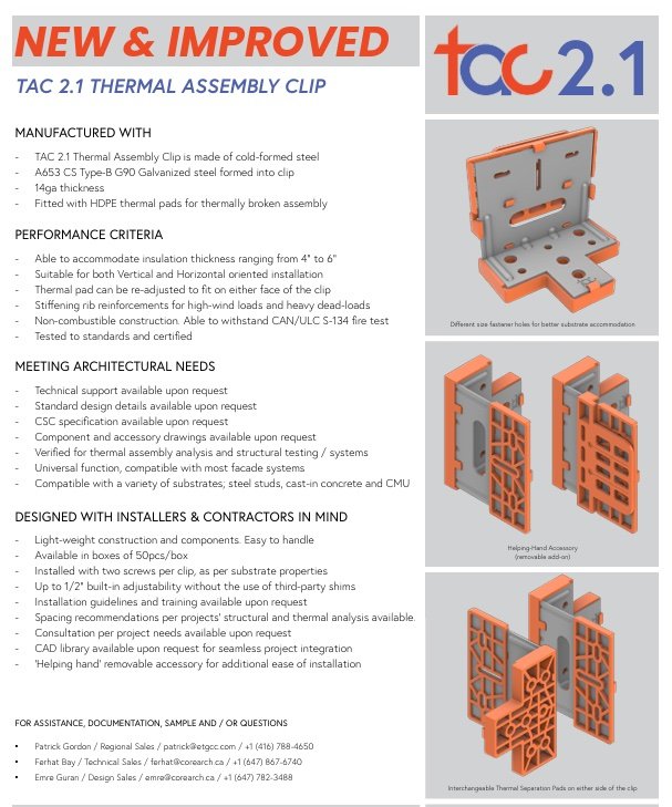
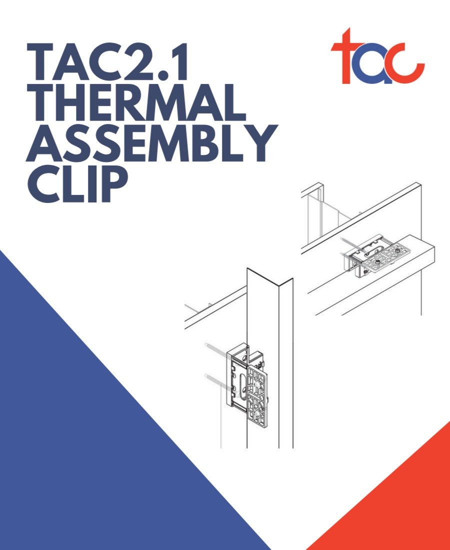
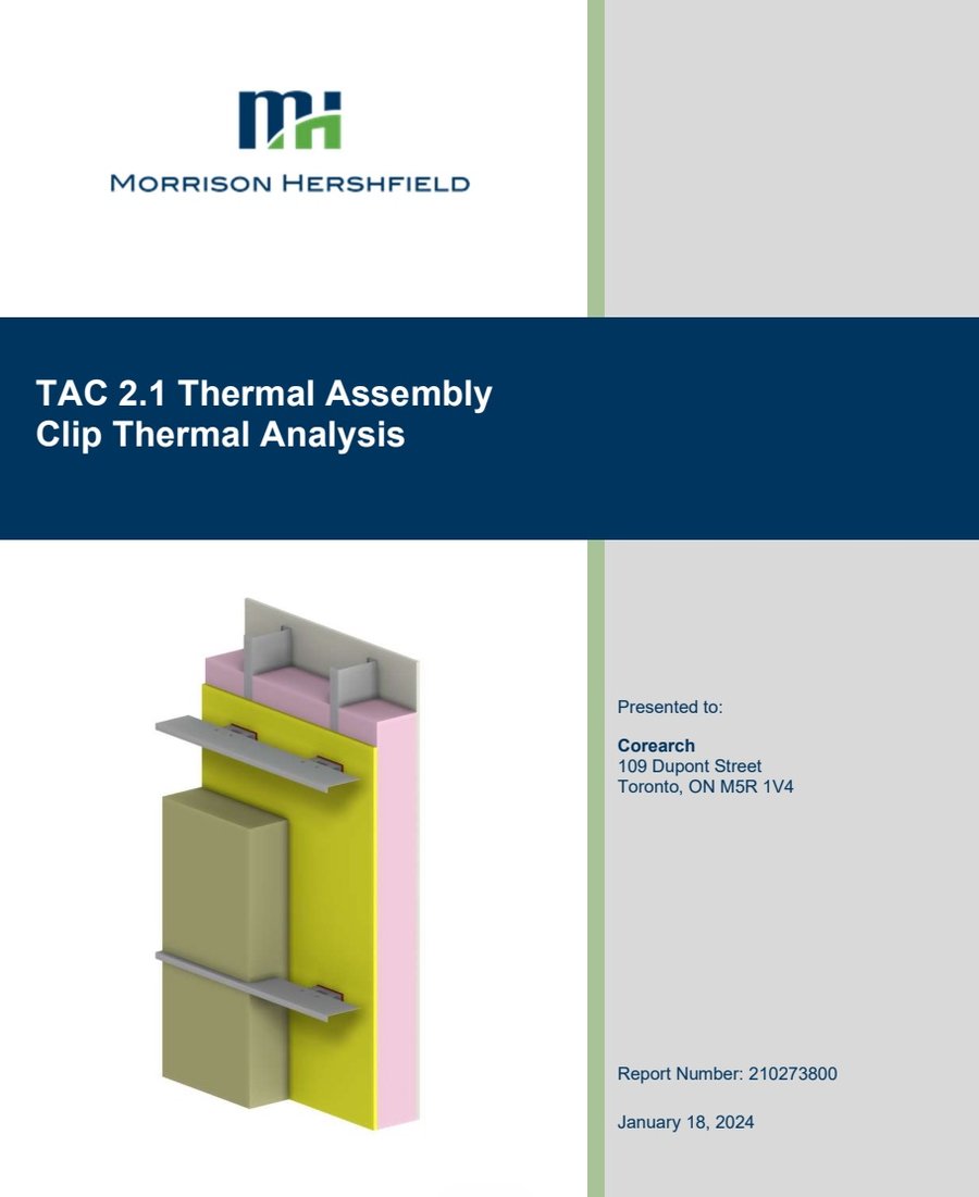
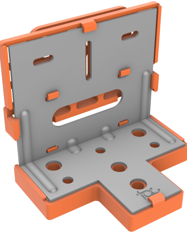
TAC 2.1 Steel
The flagship — non-combustible galvanized steel for code-driven projects.
Up to23.1 R
Effective R-Value
- Material 14GA Galvanized Steel
- Combustibility Non-Combustible
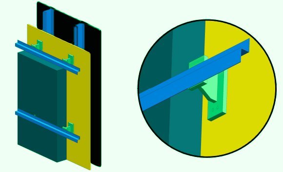
- Orientation Vertical & Horizontal
- Clip Depth 4" to 6" (with girt)